
You do not have any products added to your quote.
Trouble finding a product?
Contact us.
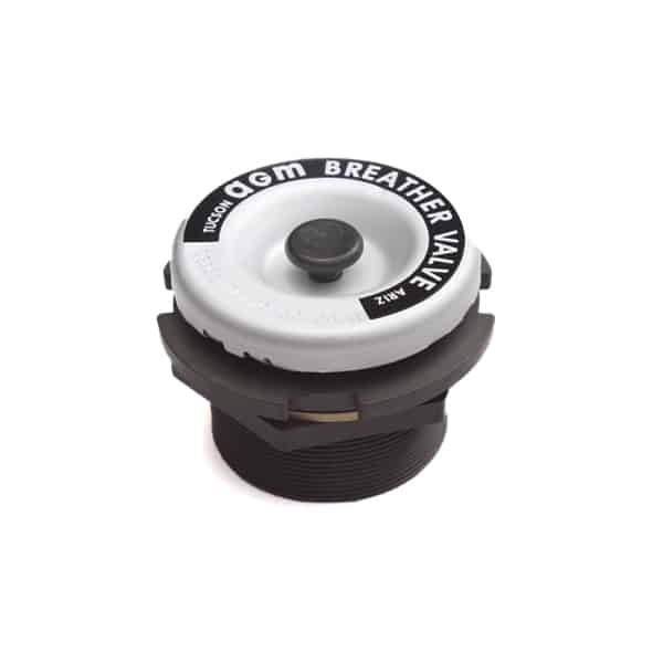
The TA770-R Breather Valve has separate and distinct settings for both pressure and vacuum relief. It has a flow rate of 10.0 to 25.0 SCFM at 1.5 psi above the valve setting, making it suitable for large containers and similar applications up to 208 cubic feet in volume. Standard settings range from 0.5 psid to 5.0 psid reseal pressure. The lower the setting, the higher the flow rate.
The TA770 Breather Valve is tamper-proof and requires no field maintenance. Corrosion-resistant materials are used throughout. The valve seal is made of silicone rubber. The spherical valve seat is Teflon coated for easy "break- away" action even after prolonged storage.
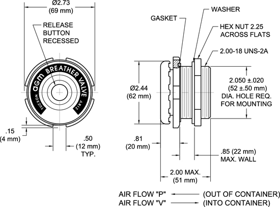
The manual release push button is used to equalize the pressure or vacuum differentials in order to make opening the container easier. The button is recessed in the cover to protect it from damage and eliminate the possibility that an adjacent container might press the button and inadvertently cause the valve to remain open. A unique feature of the push button is a light duty spring under the cover, separating the button from the vacuum stem, which must be overcome before the button opens the valve.
A gasket, washer and hex nut for mounting are provided with each valve. RFI/EMI shielding is also available. TA770-R Valves may be equipped with a rear-mounted High Flow Filter, which can also incorporate RFI/EMI shielding.
The TA770 Breather Valve's unique cover and dust baffle provides superior protection from sand and dust intrusion. Additionally, the cover makes this valve well suited for high-pressure hose down applications. When compared to a screened valve such as AGM's TA238 Breather Valve as well as competitors' valves, the TA770 Breather Valve allows virtually no water to pass when subjected to a high-pressure water stream. The TA770 Breather Valve has been tested to the NEMA 250 5.7 high-pressure hose down test; contact AGM's Engineering department for more information.
Cracking ("C") valves and reseal valves are mechanically and functionally identical, with the only distinction being their performance settings. Reseal valves are designed to meet the reseal and cracking pressure ranges outlined in the SAE AS27166 and MIL-DTL-27166 breather valve standards, while cracking valves are designed for customers seeking a nominal cracking pressure in standard increments, such as 0.25 psi, 0.5 psi, 1 psi, 2 psi, and so on. Since both types of valves are rated for both cracking and reseal pressures, simply select the valve with the settings that best suit your application, regardless of whether it is labeled as a cracking or reseal valve.
Note that whether you are specifying a reseal valve or a cracking valve, the flow rate is usually the most important parameter when selecting a valve: per SAE Specification AS27166, you should select a valve with a flow rate of at least 12% of the container volume per minute at a pressure less than the container’s pressure rating. For instance, when choosing a valve for a container with a volume of 10 cubic feet that can withstand a pressure of 2 psi, the recommended valve would flow 1.2 standard cubic feet per minute (SCFM) at 2 psid or less pressure differential. While at first glance it may appear that a valve with a crack point of 2 psi would be appropriate for this application, remember that the flow rate at crack is very low (1 cc/min) and therefore would very likely not provide adequate pressure relief.
Flow rate versus pressure curves are available for some valves. Contact AGM’s Engineering Department if you require this information.
| Materials | Housing, Hex Nut & Washer - Aluminum, Gasket - A-A-59588 Class II Grade 60 |
| Finish | Housing, Nut & Washer - Anodize |
| Mounting Requirements | Gasket, washer & hex nut, provided with each valve |
| Mounting Hole Diameter | 2.050 ± 0.020 (52 ± 0.50 mm) |
| Maximum Wall Thickness | 0.75 (19 mm) * |
| Minimum Wall Thickness | 0.001 (0.03 mm) * |
| Installation Torque | 80-90 in. - lbs. (9.0-10.0 N•m) |
| Weight | 0.40 lbs. (181 grams) |
*For threaded boss installation: 2.00-18 UNS-2B; 2.050 ± 0.020 (52 ± 0.50 mm) diameter X 0.085 (2 mm) minimum deep counterbore required for thread relief.
Contact AGM's Engineering department for information on NEMA and IP ratings.
View AGM's TA770-R Technical Drawing
RESEAL VALVES
|
PRESSURE SIDE (FLOW OUT)
|
VACUUM SIDE (FLOW IN)
|
||||
|
Dash No.
|
Sealed @
|
Flow Rate @ Pressure
|
Dash No.
|
Sealed @
|
Flow Rate @ Pressure
|
|
-05
|
0.5 psid*
|
20 SCFM @ 2.0 psid
|
-05
|
0.5 psid*
|
25 SCFM† @ 2.0 psid
|
|
-10
|
1.0 psid*
|
18 SCFM @ 2.5 psid
|
-10
|
1.0 psid*
|
23 SCFM† @ 2.5 psid
|
|
-15
|
1.5 psid*
|
16 SCFM @ 3.0 psid
|
-15
|
1.5 psid*
|
21 SCFM† @ 3.0 psid
|
|
-20
|
2.0 psid*
|
14 SCFM @ 3.5 psid
|
-20
|
2.0 psid*
|
19 SCFM† @ 3.5 psid
|
|
-25
|
2.5 psid*
|
12 SCFM @ 4.0 psid
|
-25
|
2.5 psid*
|
17 SCFM† @ 4.0 psid
|
|
-30
|
3.0 psid*
|
10 SCFM @ 4.5 psid
|
-30
|
3.0 psid*
|
15 SCFM† @ 4.5 psid
|
|
-35
|
3.5 psid*
|
8 SCFM @ 5.0 psid
|
-35
|
3.5 psid*
|
10 SCFM† @ 5 psid
|
|
-50
|
5.0 psid*
|
10 SCFM @ 8.5 psid
|
-50
|
5.0 psid*
|
10 SCFM† @ 8.5 psid
|
*To convert psid to millibars, multiply by 69. †To convert SCFM to liters/sec, multiply by 0.472.
Dash numbers for the Pressure and Vacuum sides may be used in any combination (i.e. TA770-05-15-R). AGM can also supply TA770-R Valves with other settings than those shown above. Please contact AGM for availability. Before making drawings of these valves, contact AGM for part numbers to be used.
CRACKING VALVES
|
PRESSURE SIDE (FLOW OUT) |
VACUUM SIDE (FLOW IN) |
||||
|
Dash No.
|
Cracking @*
|
Flow Rate @ Pressure
|
Dash No.
|
Cracking @*
|
Flow Rate @ Pressure
|
|
-005C
|
0.05 ± 0.05 psid
|
5.0 SCFM @ 0.3 psid
|
-005C
|
0.05 ± 0.05 psid
|
5.0 SCFM @ 0.3 psid
|
|
-025C
|
0.25 ± 0.10 psid
|
12 SCFM @ 0.75 psid
|
-025C
|
0.25 ± 0.10 psid
|
14 SCFM @ 0.75 psid
|
|
-05C
|
0.50 ± 0.25 psid
|
20 SCFM @ 1.75 psid
|
-05C
|
0.5 ± 0.25 psid
|
25 SCFM @ 1.75 psid
|
|
-10C
|
1.0 ± 0.25 psid
|
20 SCFM @ 2.0 psid
|
-10C
|
1.0 ± 0.25 psid
|
20 SCFM @ 2.0 psid
|
|
-15C
|
1.5 ± 0.20 psid
|
20 SCFM @ 3.0 psid
|
-15C
|
1.5 ± 0.20 psid
|
20 SCFM @ 3.0 psid
|
|
-20C
|
2.0 ± 0.25 psid
|
16 SCFM @ 3.0 psid
|
-20C
|
2.0 ± 0.25 psid
|
21 SCFM @ 3.0 psid
|
|
-25C
|
2.5 ± 0.25 psid
|
14 SCFM @ 3.5 psid
|
-25C
|
2.5 ± 0.25 psid
|
19 SCFM @ 3.5 psid
|
|
-30C
|
3.0 ± 0.30 psid
|
10 SCFM @ 4.5 psid
|
-30C
|
3.0 ± 0.3 psid
|
15 SCFM @ 4.5 psid
|
|
-50C
|
5.0 ± 0.50psid
|
10.5 SCFM @ 7.0 psid
|
-50C
|
5.0 ± 0.5 psid
|
10.5 SCFM @ 7.0 psid
|
*To convert psid to millibars, multiply by 69. †To convert SCFM to liters/sec, multiply by 0.472.
Dash numbers for the Pressure and Vacuum sides may be used in any combination (i.e. TA770-05C-15C). AGM can also supply TA770-R Valves with other settings than those shown above. Please contact AGM for availability. Before making drawings of these valves, contact AGM for part numbers to be used.
While typically configured as a two-way valve, this valve can also be configured for one-way flow. Refer to the TA770-R drawing for two-way performance settings, and select the setting for the direction you need. For example, part number TA770-P-30 is the one-way pressure relief version of part number TA770-30-30-R, while part number TA770-VR-30 is the one-way vacuum relief version. The vacuum relief version of the valve includes a manual release, but the pressure relief version does not. Contact AGM's Engineering Department for assistance, if needed.
|
PRESSURE SIDE (FLOW OUT)
|
VACUUM SIDE (FLOW IN)
|
||||||
|
Dash No.
|
Cracking Pressure *
|
Reseal Pressure *
|
Flow Rate *
|
Dash No.
|
Cracking Pressure *
|
Reseal Pressure *
|
Flow Rate *
|
|
-P-025
|
0.25-0.75 psid
|
0.25 psid
|
21 SCFM @ 1.75 psid
|
-VR-025
|
0.25-0.75 psid
|
0.25 psid
|
26 SCFM† @ 1.75 psid
|
|
-P-05
|
0.50-1.00 psid
|
0.5 psid
|
20 SCFM @ 2.0 psid
|
-VR-05
|
0.50-1.00 psid
|
0.5 psid
|
25 SCFM† @ 2.0 psid
|
|
-P-10
|
1.00-1.50 psid
|
1.0 psid
|
18 SCFM @ 2.5 psid
|
-VR-10
|
1.00-1.50 psid
|
1.0 psid
|
23 SCFM† @ 2.5 psid
|
|
-P-15
|
1.50-2.25 psid
|
1.5 psid
|
16 SCFM @ 3.0 psid
|
-VR-15
|
1.50-2.25 psid
|
1.5 psid
|
21 SCFM† @ 3.0 psid
|
|
-P-20
|
2.00-3.00 psid
|
2.0 psid
|
14 SCFM @ 3.5 psid
|
-VR-20
|
2.00-3.00 psid
|
2.0 psid
|
19 SCFM† @ 3.5 psid
|
|
-P-25
|
2.50-3.50 psid
|
2.5 psid
|
12 SCFM @ 4.0 psid
|
-VR-25
|
2.50-3.50 psid
|
2.5 psid
|
17 SCFM† @ 4.0 psid
|
|
-P-30
|
3.00-4.00 psid
|
3.0 psid
|
10 SCFM @ 4.5 psid
|
-VR-30
|
3.00-4.00 psid
|
3.0 psid
|
15 SCFM† @ 4.5 psid
|
*To convert psid to millibars, multiply by 69. †To convert SCFM to liters/sec, multiply by 0.472.
Before making drawings of these valves, contact AGM for part numbers to be used.
| Materials | Housing, Hex Nut & Washer-Aluminum Alloy, Gasket-A-A-59588, Class II, Grade 60 |
|---|---|
| Finish | Housing, Nut & Washer-Anodize |
| Mounting Requirements | Gasket, Washer, Hex Nut are provided with each valve |
| Mounting Hole Diameter | 2.050 ± 0.020 (52 ± 0.50 mm) |
| Maximum Wall Thickness | 0.75 in. (19 mm) |
| Minimum Wall Thickness | 0.001 in. (0.03 mm) |
| Installation Torque | 80-90 in. – lbs. (9.0-10.0 N•m) |
| Weight | 0.40 lbs. (181 grams) |
| Complies WIth | MIL-DTL-27166, SAE AS27166, U.S. Navy drawing 6212863 |