
You do not have any products added to your quote.
Trouble finding a product?
Contact us.
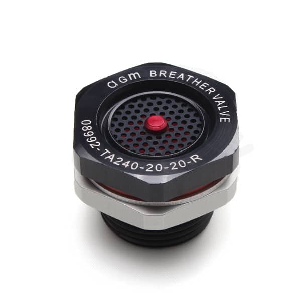
The TA240-R is a hybrid of the TA333-R Breather Valve and TA238 Breather Valve. It combines the mounting thread size and hex shape of AGM's TA333-R Breather Valve with the screened cover and lower cost of AGM's TA238 Breather Valve. The valve can be used on transit cases and similar applications up to 33 cubic feet in volume. It has a flow rate of 1.5 to 4.0 SCFM at 1.5 psid above the reseal setting and is available in settings from 0.5 psid to 5.0 psid. The valve is lightweight, rugged, tamper-proof and requires no field maintenance. Corrosion-resistant materials are used throughout. The valve seal is made of silicone rubber. A recessed manual release push button is standard on all TA240-R Breather Valves. It is used to equalize residual pressure or vacuum differentials in order to open the container. Gasket, washer and hex nut are provided with each valve. As indicated below, the lower the setting, the higher the flow rate. Mounting Flanges and RFI/EMI shielding are available for this valve. For additional enclosure protection, AGM can develop a custom desiccant cartridge that mates with the valve.
The TA240 Breather Valve will not provide protection against water intrusion from a high-pressure hose down. Use a TA330, TA333 or TA770 Breather Valve for applications where this is required.
| Materials | Housing, Hex Nut & Washer - Aluminum Alloy, Gasket - Silicone Rubber per ZZ-R-765 |
| Finish | Housing - Black anodize, Washer & Nut - Clear anodize * |
| Mounting Requirements | Gasket, washer & hex nut, provided with each valve |
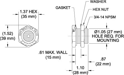
| Mounting Hole Diameter | 1.05 ± 0.015 (27 ± 0.38 mm) |
| Maximum Wall Thickness | 0.61 (15 mm) * |
| Installation Torque | 30-40 in. - lbs. (3.4-4.5 N•m) |
| Weight | 0.02 lbs. (32 grams) |
*Add extra washer for wall thickness less than .04 (1 mm). (AGM P/N 300013-16, order separately.)
For threaded boss installation: 3/4-14 NPSM; 1.05 ± 0.015 (27 ± 0.38 mm) X 0.08 (2 mm) minimum deep counterbore required for thread relief.
Contact AGM's Engineering department for information on NEMA and IP ratings.
|
PRESSURE SIDE (FLOW OUT)
|
VACUUM SIDE (FLOW IN)
|
||||
|
Dash No.
|
Sealed @
|
Flow Rate @ Pressure
|
Dash No.
|
Sealed @
|
Flow Rate @ Pressure
|
|
-05
|
0.5 psid*
|
3.0 SCFM† @ 2.0 psid*
|
-05
|
0.5 psid*
|
4.0 SCFM† @ 2.0 psid*
|
|
-10
|
1.0 psid*
|
2.5 SCFM† @ 2.5 psid*
|
-10
|
1.0 psid*
|
3.0 SCFM† @ 2.5 psid*
|
|
-15
|
1.5 psid*
|
2.5 SCFM† @ 3.0 psid*
|
-15
|
1.5 psid*
|
3.0 SCFM† @ 3.0 psid*
|
|
-20
|
2.0 psid*
|
2.5 SCFM† @ 3.5 psid*
|
-20
|
2.0 psid*
|
2.5 SCFM† @ 3.5 psid*
|
|
-25
|
2.5 psid*
|
1.5 SCFM† @ 4.0 psid*
|
-25
|
2.5 psid*
|
1.5 SCFM† @ 4.0 psid*
|
*To convert to metric equivalent (millibars) multiply by 69
†To convert metric equivalent (liters/sec) multiply by 0.472
Dash numbers for the Pressure and Vacuum sides may be used in any combination
(i.e. TA240-05-15-R). AGM can also supply TA240-R Valves with other settings than
those shown above. Please contact AGM for availability. Before making drawings of
these valves, contact AGM for part numbers to be used.
While typically configured as a two-way valve, this valve can also be configured for one-way flow. For example, part number TA240-P-30 is the one-way pressure relief version of part number TA240-30-30-R, while part number TA240-VR-30 is the one-way vacuum relief version. The vacuum relief version of the valve includes a manual release, but the pressure relief version does not. Contact AGM's Engineering Department for assistance, if needed.
|
PRESSURE SIDE (FLOW OUT)
|
VACUUM SIDE (FLOW IN)
|
||||||
|
Dash No.
|
Cracking Pressure *
|
Reseal Pressure *
|
Flow Rate *
|
Dash No.
|
Cracking Pressure *
|
Reseal Pressure *
|
Flow Rate *
|
|
-P-025
|
0.25-0.75 psid
|
0.25 psid
|
4.0 SCFM† @ 1.75 psid
|
-VR-025
|
0.25-0.75 psid
|
0.25 psid
|
4.0 SCFM† @ 1.75 psid
|
|
-P-05
|
0.50-1.00 psid
|
0.5 psid
|
3.0 SCFM† @ 2.0 psid
|
-VR-05
|
0.50-1.00 psid
|
0.5 psid
|
4.0 SCFM† @ 2.0 psid
|
|
-P-10
|
1.00-1.70 psid
|
1.0 psid
|
2.5 SCFM† @ 2.5 psid
|
-VR-10
|
1.00-1.70 psid
|
1.0 psid
|
3.0 SCFM† @ 2.5 psid
|
|
-P-15
|
1.50-2.25 psid
|
1.5 psid
|
2.5 SCFM† @ 3.0 psid
|
-VR-15
|
1.50-2.25 psid
|
1.5 psid
|
3.0 SCFM† @ 3.0 psid
|
|
-P-20
|
2.00-3.00 psid
|
2.0 psid
|
2.5 SCFM† @ 3.5 psid
|
-VR-20
|
2.00-3.00 psid
|
2.0 psid
|
2.5 SCFM† @ 3.5 psid
|
|
-P-25
|
2.50-3.50 psid
|
2.5 psid
|
1.5 SCFM† @ 4.0 psid
|
-VR-25
|
2.50-3.50 psid
|
2.5 psid
|
1.5 SCFM† @ 4.0 psid
|
|
-P-30
|
3.00-4.00 psid
|
3.0 psid
|
1.5 SCFM† @ 4.5 psid
|
-VR-30
|
3.00-4.00 psid
|
3.0 psid
|
1.5 SCFM† @ 4.5 psid
|
*To convert psid to millibars, multiply by 69. †To convert SCFM to liters/sec, multiply by 0.472.
Before making drawings of these valves, contact AGM for part numbers to be used.
| Materials | Housing, Hex Nut & Washer-Aluminum Alloy, Gasket-Silicone Rubber per ZZ-R-765 |
|---|---|
| Finish | Housing-Black Anodize, Washer & Nut-Clear Anodize |
| Mounting Requirements | Gasket, Washer, Hex Nut are provided with each valve |
| Mounting Hole Diameter | 1.05 ± 0.015 (27 ± 0.38 mm) |
| Maximum Wall Thickness | 0.61 in (15 mm) |
| Installation Torque | 30-40 in. – lbs (3.4-4.5 N-m) |
| Weight | 0.02 lbs (32 grams) |
| Complies With | MIL-DTL-27166, SAE AS27166 |