
You do not have any products added to your quote.
Trouble finding a product?
Contact us.
AGM shock indicators mark an occurrence of shock, impact and vibration in excess of a chosen threshold. This helps to ensure that products are not mishandled during shipment.
It’s a lot, we know. If you’re looking for something specific or aren’t sure what you need, try searching through all products or give us a shout and we’ll help!
Shock indicators are small mechanical or electromechanical devices designed to indicate the occurrence of impacts and vibrations that are in excess of a given threshold, typically while in transport. With this indication, it is possible to identify specific units that require review as to determine potential damage from the shock. Shock indicators can be set up to monitor along specific axes.
Shock indicators differ from shock recorders in a few important ways.
In a shock indicator, an impact of sufficient magnitude will trigger some function, typically a mechanical or electromechanical mechanism, in the device such that an inspector will see that a potentially damaging shock has occurred. This function may or may not record the magnitude of the indicated impact. However, the device threshold will be notated on the device itself so anyone looking at the device will know that, if triggered, the impact is in excess of that threshold. These devices are especially useful when an electrical device is not ideal and an analogue option is desired.
In contrast, a shock recorder will actively record data (magnitude, direction, duration) on shocks and vibrations it experiences. This data can then be recovered later for analysis; however, some models can send data in real time.
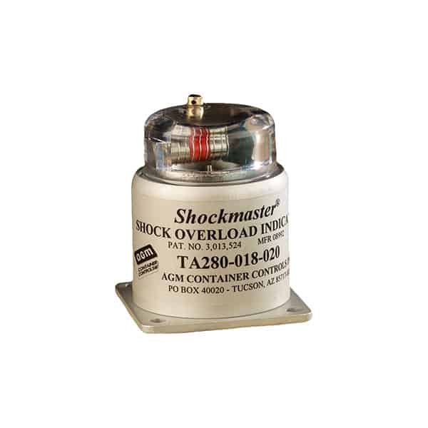
Our shock indicator, the Shockmaster, consists of a spring-loaded weight with an integral trigger that engages with a spring-loaded sleeve, the entire assembly being enclosed in a metal housing with a transparent dome.
When a shock occurs, the weight is forced down against its spring. If the shock is of sufficient magnitude, the trigger is disengaged from the sleeve, which, in turn, is forced by its own spring to move along a rod, exposing a red warning band.
For more specific information regarding the AGM Shockmaster, see the product page.
1. Reduce product and cargo inspection times: If a Shockmaster shock indicator has not been tripped, then terminal inspection time can be reduced substantially as only those shipments with tripped indicators needed to be reinspected in detail.
2. Help cut shipping and handling costs: Shockmasters can be used to detect when a product is being roughly handled or damaged in the supply chain. Corrective measures may then be initiated to improve material handling procedures. The Shockmaster is also an invaluable tool for shock tests to determine proper packaging design and materials. A row of indicators—each set for tripping at a different G-rating— may be used in container drop tests, thereby detecting both overpackaging and underpackaging of a product.
3. Tamper-Proof: To prevent tampering with the indicator after it has been tripped, a safety wire with an inspector’s seal attached can be placed through the resetting hole screws in the plastic dome. Or, the inspector’s decals may be affixed over the reset holes. Shockmasters with ratings of 25 Gs or more are made tamper-proof by re-inserting one screw, threading safety wire through holes in the plunger and screw head and securing with an inspector’s seal.
4. Reusable: Shockmasters can be used over and over again. After tripping, the indicator is reset by removing the screw from the threaded hole in the side of the dome, inserting a stiff wire or straightened paper clip in the hole and pushing the black sleeve back to its armed position. For Shockmasters with ratings of 25 Gs or more, a plunger in the dome is depressed while the sleeve is pushed back as far as possible. The plunger is then released and the sleeve is allowed to return gently to its armed position.
Many defense supplier customers use our shock indicators during the transport of missiles and large electronics equipment. Shock indicators can also be used on sea shipments to indicate whether the cargo containers have experienced rough conditions on a level that would warrant an inspection.
No two jobs are the same. so get the solution that’s right for you
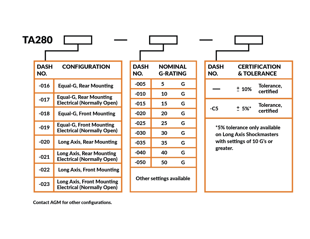
The chart below details how to choose which shock indicator, or Shockmaster, configuration meets the requirements of a given application.
Part numbers consist of a basic number, followed by a series of dash numbers, designating configuration, nominal G-rating, and certified tolerance.
Example: TA280-022-015-C5 is a Long Axis, Front Mounting Shockmaster set for 15 G’s with a +/-5% tolerance, certified.
Models TA280-016, TA280-020, TA280-017 and TA280-021 can be mounted with 4 No. 6-32 machine screws from the rear. Models having a square adapter plate, such as Shockmasters TA280-018, TA280-022, TA280-019 and TA280-023, can be mounted from the top with 4 No. 6 wood screws or machine screws. The Shock Indicator may be mounted on the container or on the packaged item. If it is mounted on the container, it will indicate the handling which the package as a whole has experienced. This way of mounting essentially checks on the handling methods. If the Shock Indicator is mounted on the packaged item, then the recorded shocks will be less severe due to damping by the packaging materials, such as isolators, foam cushioning, corrugated cardboard, etc. This type of mounting will indicate the amount of shock to which the packaged product was subjected.
Models TA280-016, TA280-017, TA280-018 and TA280-019 are sensitive to all acceleration forces except those coming from the top (i.e. passing through the hemisphere occupied by the plastic dome). Two equal-G Shockmasters mounted back-to-back will cover shocks from all possible directions. For long containers, it will be advantageous to have a Shock Indicator at each end of the package. Models TA280-020, TA280-021, TA280-022 and TA280-023 have longitudinal response and will only trip if subjected to axial shocks applied to the bottom of the Shockmasters. Side or transverse shocks have no effect.
When mounting a Shockmaster, it is important to consider the direction of the anticipated shock. For example, a Shockmaster with the plastic dome up will trip when banged on a table. In this case, the shock has come from the bottom of the Shock Indicator. This impact reflects what would occur if a box were dropped. On the other hand, if a Shockmaster is installed dome up in a vehicle which collides with an obstacle, the shock would come from the side of the Shock Indicator.
The Shockmaster consists of a spring-loaded weight with an integral trigger which engages with a spring-loaded sleeve. When tripped, this sleeve moves along a guide rod and exposes a red band on this rod. The upper periphery of the weight rests against a shoulder. The whole assembly is enclosed in a metal housing and transparent dome.
If the shock is applied to the unit along the long axis, the weight will be forced down against the spring. If the shock is applied from any side direction, the weight tips against the spring. Either movement disengages the trigger from the sleeve, which then moves under the action of its spring, exposing the red band. The Shock Indicator is now tripped. It can be reset by inserting a wire, such as a straightened paper clip, into the hole on the side of the dome and pushing the sleeve back to its armed position. For models of 25 G and over, a plunger in the dome is depressed while the sleeve is pushed back.
In most cases, it is advisable to seal the resetting holes after resetting. This may be done by inserting 2 No. 4-40 screws with drilled heads into the two holes in the dome, safety wiring them and sealing the wire with an inspector’s seal. Shockmasters with ratings of 25 G’s or more are made tamper-proof by re-inserting one screw, threading safety wire through the holes in the plunger and screw head and securing with an inspector’s seal.
AGM’s guarantee of proper functioning of the Shockmaster under environmental conditions of dust, sand, moisture, etc., is dependent upon the proper sealing of the resetting holes. CAUTION: The transparent dome is easily damaged by solvents and thread locking solutions. RTV has been found to be suitable for sealing screw heads against dust and moisture intrusion.
Models TA280-019, TA280-021 and TA280-023 with electrical contacts can be used to check the Shockmaster condition inside a package without opening it. If this type of Shock Indicator is enclosed inside a box or attached to the packaged item, wires can be run to the outside of the box and terminated there, either in pigtails or in suitable connectors. Do not solder to these connectors as this will damage the shelter. These wires must be crimped to the terminals on top of the dome. Polarity is immaterial. The condition of the Shock Indicator can then be determined from the outside by a simple continuity check with a portable ohmmeter, for instance, or with a dry cell and a light bulb. The contacts will be closed when the Shockmaster is tripped.
If the Shockmasters have to be tested for conformance with performance specifications published here or elsewhere, the tests must be carried out in accordance with AGM’s test specifications. These specifications will be made available upon request.
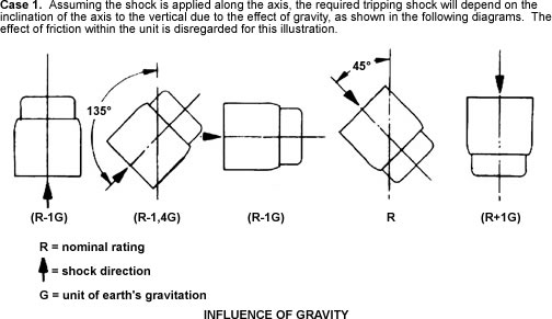
The nominal rating is defined as the acceleration along the longitudinal axis (expressed in G’s) necessary to trip the Shock Indicator mounted with axis vertical in gravity free space when applied for infinite time.
The response of the unit to a shock will vary with (A) the duration of the shock or (B) the effects of gravity and shocks coming from directions at an angle other than the Shockmaster’s longitudinal axis or transverse plane.
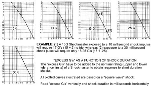
(A) If the duration of the shock is short, say below 30 milliseconds, an acceleration in excess of the nominal rating will be needed to trip the unit. The following graphs approximate the “excess G’s” required as a function of the shock duration for the most common G-ratings. These graphs are based on a “theoretical square wave” type shock. The “excess G’s” have to be added to the nominal rating to obtain the response to short duration shocks.
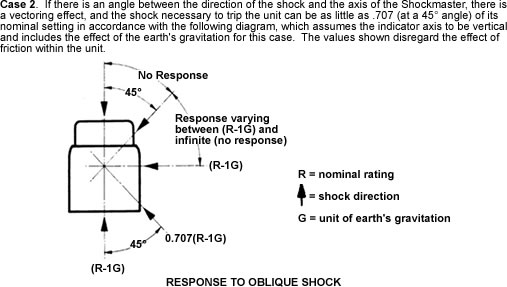
(B) Due to the effect of gravity, the attitude of the unit to the vertical varies the magnitude of tripping acceleration required. The relation of the direction of the applied acceleration to the vertical and the unit axis, also varies the magnitude of the tripping acceleration.
Case 3. The effects of cases 1 and 2 may be combined and even further complicated by having the vertical, the longitudinal axis and the direction of the shock not in the same plane. Also, units with sensitivity only in one direction present a special situation. The effects of friction may be disregarded in settings of 10 G’s or greater.
(C) Tolerance of the rating is ±10% or ±5%*. Shock Indicators are certified to be inside the specified tolerances when mounted as shown in Case 2 (above). Tolerances and certification are indicated by the model number. For instance:
TA280-016-010 = Nominal rating of 10 G, Accuracy ±10%, certified.
TA280-016-010C5 = Nominal rating of 10 G, Accuracy±5%, certified.
*5% tolerance not available on settings below 10 G’s.

The Shockmaster is a low-cost, compact mechanical device that can be installed on delicate equipment to detect excessive shock and vibration, thereby assisting in the detection of hidden damage.
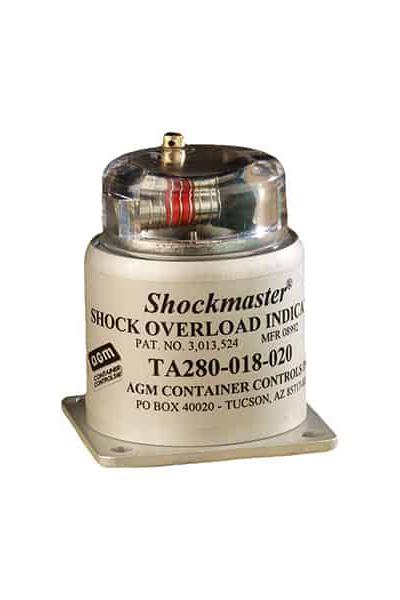
The Shockmaster consists of a spring-loaded weight with an integral trigger which engages with a spring-loaded sleeve, the entire assembly being enclosed in a metal housing with a transparent dome. When a shock occurs, the weight is forced down against its spring. If the shock is of sufficient magnitude, the trigger is disengaged from the sleeve, which, in turn, is forced by its own spring to move along a rod, exposing a red warning band.
Since the springs in the Shockmaster are never elongated, it will remain in tolerance indefinitely, provided it is not subjected to continuous motion of the moving parts and is not contaminated internally with foreign particles.
No. Our products only monitor shock impact. However, one of the primary goals of using AGM’s shock impact indicator products is to build awareness in those individuals and companies handling your products. The result should be better handling or improved ability to prove mishandling; either way, the end result will be a reduction in damage to your products.
he Shockmaster has a hemispheric response: it indicates shocks from all directions radial to the unit, axial shocks to the base from beneath, and shocks from all directions between these planes. It will not register axial shocks applied to the dome from above. Models are also available with axial (base) response only. Two Shockmasters are usually sufficient for even the largest of packaged items, and one may be adequate if there is no possibility of the equipment being shocked from above.
Yes. Shockmasters can be used over and over again. After tripping, the indicator is reset by removing the screw from the threaded hole in the side of the dome, inserting a stiff wire or straightened paper clip in the hole and pushing the black sleeve back to its armed position. For Shockmasters with ratings of 25 Gs or more, a plunger in the dome is depressed while the sleeve is pushed back as far as possible. The plunger is then released and the sleeve is allowed to return gently to its armed position.
Standard Shockmasters trip within ±10% of their settings. On units set for 10 Gs or higher, tolerances of ±5% are available at an extra cost. They operate from -80°F to 160°F and are resistant to high humidity.
They operate from -80°F to 160°F and are resistant to high humidity.
Yes. To prevent tampering with the indicator after it has been tripped, a safety wire with an inspector’s seal attached can be placed through the resetting hole screws in the plastic dome. Or, inspector’s decals may be affixed over the reset holes. Shockmasters with ratings of 25 Gs or more are made tamper-proof by re-inserting one screw, threading safety wire through holes in plunger and screw head and securing with an inspector’s seal.
Shockmasters may be mounted on the inside of the container or directly on the packaged item.. There are four mounting holes in the base for rear mounting, or a mounting plate is available for front mounting of the units.
Inspection may be accomplished by looking at the indicator through a hole with a removable cover in the container. Or, a Shockmaster with electrical contacts may be used. This model can be inspected by placing the leads of an ohmmeter, or a battery and light bulb, on the contacts of a terminal board mounted on the outside of the container. If the Shockmaster is tripped, the ohmmeter will indicate that the circuit is closed, or the light bulb will glow.
Shockmasters are available from stock in nominal ratings of 5, 10, 20, 25, 30, 35, 40 and 50 Gs. Other settings are available upon request. The standard equal-G models respond equally to shocks along the longitudinal axis and in the transverse plane. The standard long axis models respond to longitudinal axis shock only—side or transverse shocks have no effect.
In three ways:
(1) Shock indicators can be used to detect rough handling of a product on assembly lines or in other areas of your plant. Corrective measures may then be initiated to improve material handling procedures.
(2) Shock indicators are an invaluable tool for shock tests to determine proper packaging design and materials. A row of indicators—each set for tripping at a different G-rating— may be used in container drop tests, thereby detecting both overpackaging and underpackaging of a product.
(3) Terminal inspection time can be reduced substantially, as only those shipments with tripped indicators need be reinspected in detail.
It’s a lot, we know. If you’re looking for something specific or aren’t sure what you need, try searching through all products or give us a shout and we’ll help!