
You do not have any products added to your quote.
Trouble finding a product?
Contact us.
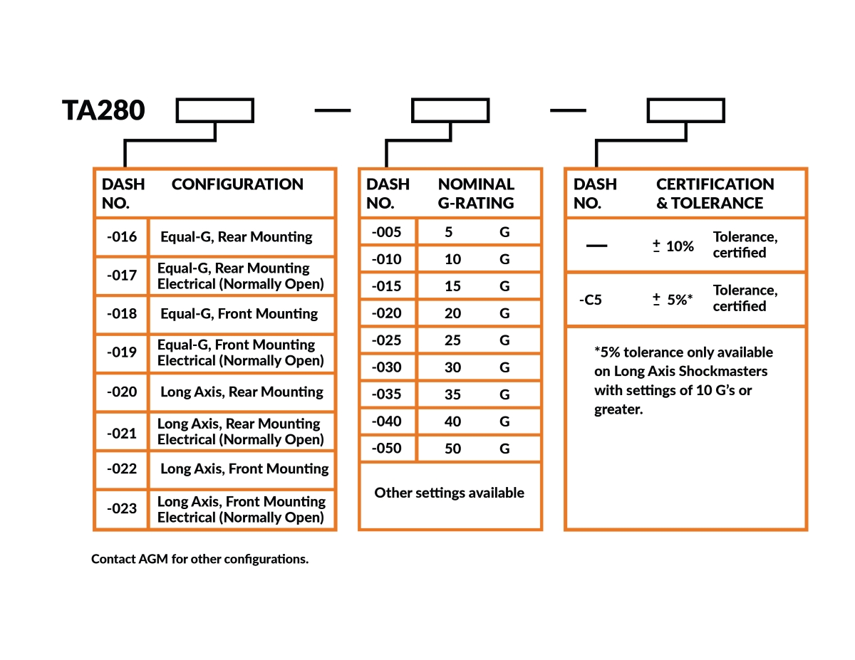
The TA280 shock indicators part numbers consist of a basic number, followed by a series of dash numbers, designating configuration, nominal G-rating, and certified tolerance.
Example: TA280-022-015-C5 is a Long Axis, Front Mounting Shockmaster set for 15 G’s with a +/-5% tolerance, certified.
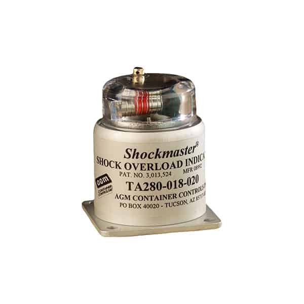
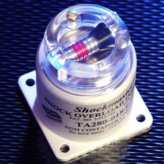
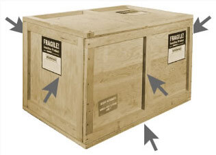
Shockmaster is a low cost, compact mechanical device which can be installed on delicate equipment to detect excessive shock and vibration, thereby assisting in the detection of hidden damage. When a container is opened, following shipment, there may appear to be no damage. However, if the shock indicators are found to be in a "tripped" condition (with bright red signal band exposed in the dome), it is evident that excessive shock has been experienced. Accordingly, a thorough inspection should be made before accepting the shipment.
Since the springs in the Shockmaster are never elongated, it will remain in tolerance indefinitely, provided it is not subjected to continuous motion of the moving parts and is not contaminated internally with foreign particles. The Shockmaster may be reset and used over and over hundreds of times with no change to its G-rating. Some Shockmasters have been returned for recalibration after 10 years of use, and the units were still within the original factory tolerance.
The Shockmaster has a hemispheric response: it indicates shocks from all directions radial to the unit, axial shocks to the base from beneath, and shocks from all directions between these planes. It will not register axial shocks applied to the dome from above. Models are also available with axial (base) response only. Two shock indicators are usually sufficient for even the largest of packaged items, and one may be adequate if there is no possibility of the equipment being shocked from above.
Shockmasters may be used over and over again. After tripping, the Shock Indicator is reset by removing the screw from the threaded hole in the side of the dome, inserting a stiff wire or straightened paper clip in the hole and pushing the back sleeve back to its armed position. For Shockmasters with ratings of 25 G's or more, a plunger in the dome is depressed while the sleeve is pushed back as far as possible. The plunger is then released and the sleeve is allowed to return gently to its armed position.
Standard Shockmasters trip within ±10% of their settings. On units set for 10 G's or higher, tolerances of ±5% are available at an extra cost. They operate from -80°F to 160°F and are resistant to high humidity.
To prevent tampering with the Shock Indicator after it has been tripped, a safety wire with an inspector's seal attached can be placed through the resetting hole screws in the plastic dome. Or, inspector's decals may be affixed over the reset holes. Shockmasters with ratings of 25 G's or more are made tamper-proof by re-inserting one screw, threading safety wire through holes in plunger and screw head and securing with an inspector's seal.
Shockmasters can help cut shipping and handling costs in three ways:
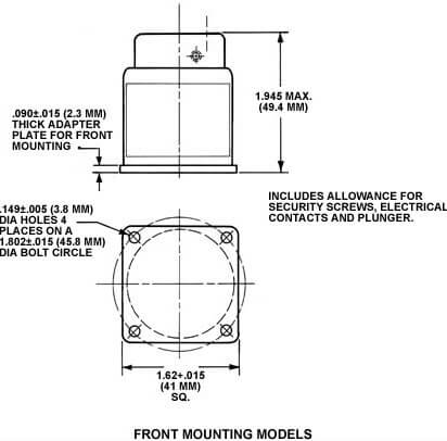
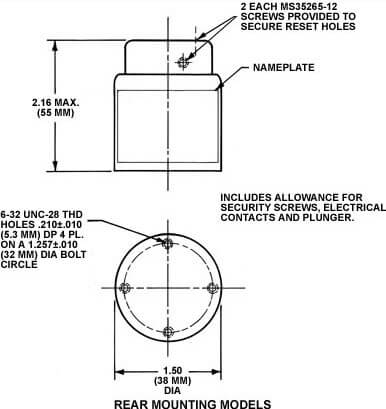
Shockmasters may be mounted on the inside of the container or directly on the packaged item. There are four mounting holes in the base for rear mounting, or a mounting plate is available for front mounting of the units.
Approximately 0.3 lbs. (136 grams), depending upon model.
The body is aluminum, clear anodized. The dome is transparent polycarbonate.
Inspection may be accomplished by looking at the indicator through a hole with a removable cover in the container. Or, a Shockmaster with electrical contacts may be used. This model can be inspected by placing the leads of an ohmmeter, or a battery and light bulb, on the contacts of a terminal board mounted on the outside of the container. If the Shockmaster is tripped, the ohmmeter will indicate that the circuit is closed, or the light bulb will glow.
Shock Indicators are available from stock in nomial ratings of 5, 10, 20, 25, 30, 35, 40 and 50 G's. Other settings are available upon request. The standard equal-G models respond equally to shocks along the longitudinal axis and in the transverse plane. The standard long axis models respond to longitudinal axis shock only - side or transverse shocks have no effect.
Independent test facilities have compared various mechanical shock-monitoring devices. Each time Shockmaster was rated the most accurate and easiest to use! Details available upon request.
To reset the Shockmaster, follow the steps listed below:
The Shockmaster is now set and ready for use.
| Body Finish | Anodized, Clear |
|---|---|
| Configuration | Equal-G, Front Mounting, Equal-G, Front Mounting Electrical (Normally Open), Equal-G, Rear Mounting, Equal-G, Rear Mounting, Electrical (Normally Open), Long Axis, Front Mounting, Long Axis, Front Mounting Electrical (Normally Open), Long Axis, Rear Mounting, Long Axis, Rear Mounting Electrical (Normally Open) |
| Body Material | Aluminum |
| Nominal G-Rating | 10 G, 15 G, 20 G, 25 G, 30 G, 35 G, 40 G, 5 G, 50 G |
| Dome Material | Transparent Polycarbonate |
| Certification Tolerance | ± 10% tolerance-certified (Standard), ± 5% tolerance-certified |