This guide breaks down the core mechanisms behind moisture ingress and pressure changes in sealed enclosures—and how to design systems that actually control them.
Moisture and pressure abatement are critical in engineering design.
The Trade Risk Guaranty reported in 2016 that roughly 10-percent of all container shipment cargo is ruined due to moisture damage. As ocean-going container shipping is a 14-trillion-dollar industry, the financial losses are extreme. In 2008, moisture ingress into several sensors resulted in the $1.4 billion crash of the B-2 “Spirit of Kansas”. Further, moisture has been cited as a possible cause of short circuiting that has led to thermal runaway in several electric vehicle fires.
The events above point to a general misunderstanding among many engineers of moisture’s behavior and moisture protection best practices as they pertain to sealed spaces. After examining questions posed by many of our own customers, AGM’s engineering team has distilled this general confusion into five points. Through a better understanding of these points, it’s possible to devise more effective moisture and pressure solutions.
This guide will discuss:
- Five points of confusion when designing moisture and pressure systems;
- Considerations for designing moisture protection;
- The interplay between pressure relief and moisture ingress;
- Moisture adsorption rates and capacities for common desiccants;
- Desiccant units and specifying quantities;
- Pressure and vacuum swings due to elevation and diurnal temperature cycling
- Understanding the difference between and importance of cracking vs full-flow pressure rating in breather valves; and,
- Integrating moisture and pressure protection.
5 THINGS TO UNDERSTAND ABOUT MOISTURE AND PRESSURE
1: WHY NO SEALED ENCLOSURE IS TRULY MOISTURE-PROOF
Nothing is ever fully sealed against moisture; moisture is pervasive and will find a way inside. Why? Moisture vapor transmission. Engineers in nearly every field must properly plan and design projects with moisture vapor transmission in mind.
MOISTURE PERMEATION THROUGH SOLID MATERIALS
Moisture will permeate through structural materials, such as those used in the construction of the enclosure itself. If a higher vapor pressure or concentration exists outside of a sealed space, moisture will dissolve on the outside of the material, conduct through it, and then evaporate inside of the enclosure. Some materials, such as plastics, have high Moisture Vapor Transmission Rates (MVTRs) and are therefore not greatly effective at preventing moisture ingress via permeation.
Basically, the lower the MVTR, the greater your dry storage time and lower moisture load on moisture mitigators, such as desiccants.
MOISTURE PERMEATION THROUGH SEALS AND GASKETS
Just as with enclosure materials, moisture will permeate through seals or gaskets in an effort to create water vapor equilibrium. Lastly, if sufficient vacuum or pressure is acting on an enclosure, its seals can fail and allow greater quantities of water vapor – or even liquid water – to ingress.
2: DON’T UNDERVALUE MOISTURE PROTECTION IN THE DESIGN PHASE
Giving due attention to moisture protection needs ahead of time can save a team from project redesigns or having to specify expensive customized desiccating solutions.
CUSTOM DESICCANTS
A frequent issue in many technical industries is the lack of available space within a product or enclosure, wherein desiccant is needed to maintain specific dryness targets. Sometimes these tight spaces are the natural result of a product’s overall size requirements. Other times, however, the restricted spaces and complex geometries available in a product’s housing or enclosure are the result of poor planning. There are two options to solve this latter issue: Custom desiccants formed to fit the available space, or project redesign.
CUSTOM DESICCANTS ARE COMMONLY EITHER BAGGED OR SOLID
Custom desiccant bags may be handsewn or heat sealed and are designed in non-standard shapes and sizes. One example is of desiccant “snakes,” featuring bulk desiccant heat sealed inside of long tubes of Tyvek® that are frequently found in the battery housings of electric vehicles.
Custom solid desiccants are normally comprised of some type of desiccant and various thermal resistant bonding agents. These desiccants typically feature significant heat resistance and crush strength but most importantly they are shapeable, commonly through press forming or machining, and are made to fit strict tolerances.
3: HOW PRESSURE DIFFERENTIALS DRIVE MOISTURE INGRESS
Creating positive pressure inside of an enclosure using a dry gas such as nitrogen will not prevent moisture from permeating through enclosure-wall materials and seals. Water molecules always move from high density to low density to achieve equilibrium, even against overall positive gas pressure.
However, moisture ingress from outside of a sealed space is not the only issue; there are two other moisture concerns from the inside: Water vapor in the air in the environment when the enclosure is sealed, and component off gassing.
When dry-gas purging to achieve internal dryness targets, removing moisture vapor from the ambient air sealed into the space is not in itself difficult. However, many materials such as PCB boards and plastics are hygroscopic and will absorb moisture during component manufacture or storage. Once inside of a sealed enclosure, these materials will off-gas their held moisture incrementally, even if the space is pressurized. It is because of this incremental off gassing that dry-gas purging may take hours or days to satisfactorily complete.
4: UNDERSTAND THE LIMITATIONS OF DESICCANT PERFORMANCE
Desiccant will not last forever. In fact, depending upon the application, desiccant may be effective for only short periods of time. For example, a desiccant packet placed in a small, well-sealed container that is then stored in a controlled environment may last for years, while a desiccant cartridge in a desiccator assembly installed in an aerial surveillance camera may last only a few flights.
As indicated from the above examples, temperature and relative-humidity levels in and around desiccated spaces play crucial roles in determining the effective lifespans of desiccants and, therefore, the changeout intervals of those desiccants. In general, desiccant can hold 18% to 32% of its weight in moisture. If your desiccants saturate before their intended changeout interval, the operational life of your project can be negatively impacted.
5: WATERPROOF VENTS (IMMERSION BREATHERS) DON’T PREVENT ALL WATER ENTRY
Perhaps ironically, waterproof vents – otherwise known as waterproof breathers, immersion breathers, GORE® vents or membrane vents – are not fully waterproof. On the contrary, while an immersion breather will prevent liquid water ingress, it will also allow the flow of water vapor. Accordingly, immersion breathers are often used on robust products or enclosures with internals that are at low-risk for moisture damage.
Note that it is not advised to use desiccants in conjunction with waterproof vents, as the ingress of water vapor will quickly saturate any desiccant. However, the forthcoming TA360 Immersible Breather Valve from AGM Container Controls will make it possible to create desiccated environments in submersible enclosures, as the valve prevents liquid water ingress even when open.
DESIGNING FOR LONG-TERM MOISTURE AND PRESSURE STABILITY
The proper planning of moisture protection in any project requires a thorough understanding of component durability, operational environment, housing and container materials, and the basic science of Relative Humidity (RH) and Dew Point.
PROPER PROTECTION: HOW DRY IS DRY ENOUGH?
Dryness targets are dependent upon the assembly. For example, the electronics in a traffic light in Phoenix, Arizona, require less stringent protection due to the environment’s typical weather conditions compared to an aerial surveillance system used at high altitude.
To better understand moisture protection, it’s important to clarify the roles that Dewpoint and RH play in determining dryness targets.
First, dewpoint is the temperature at which moisture will condense out of the air. RH states how much moisture is in the air compared to how much the air can potentially hold, and it varies with temperature.
Second, don’t worry too much about RH, concern yourself with dewpoint! Electronics and optics assemblies present themselves as good examples here.
When planning moisture protection for an electronics assembly and determining an appropriate dryness target, a general guide marker is:
Dewpoint less than -4◦C or 27◦F (or < 5000 ppm moisture, or < 21%RH at 77◦F)
Of course, this rule may vary by assembly and application; however, electronic assemblies can typically withstand some frosting, so the general goal is to avoid liquid water condensation.
When planning moisture protection for an optics assembly and determining an appropriate dryness target, a general guide marker is:
Dewpoint less than the lowest temperature that the enclosure will experience.
As is for electronic assemblies, the above rule is subject to some variation based upon application; however, with regard specifically to optics, maintaining a significantly low dewpoint is imperative to preventing fogging and maintaining proper functionality.
That said, there is great diversity among the world’s many markets, meaning that determining and achieving dryness targets – and in fact, developing a full pressure and moisture protection system – is tricky. We’ve already discussed that moisture is pervasive and there is no stopping it’s ingress; so, how is moisture best mitigated in sealed spaces? In a word, desiccants.
DESICCANTS AND HOW THEY WORK
WHAT IS DESICCANT?
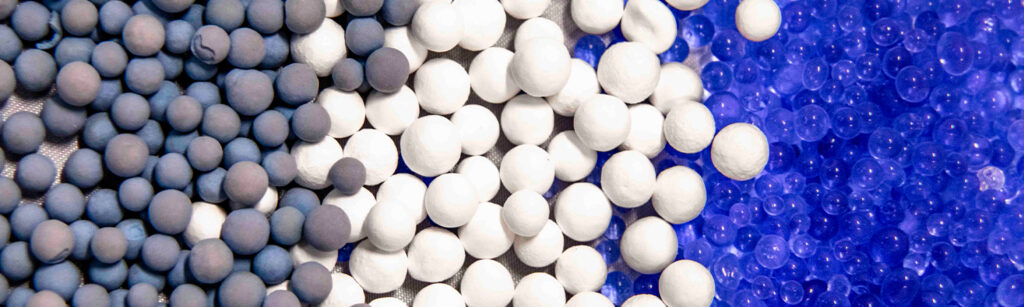
A desiccant is a material that readily attracts and holds water vapor from the air. Desiccants are both naturally-occurring and manufactured but in general are various porous materials, such as silica gel, clay, and many others. In general, desiccant will adsorb 18% to 32% of its weight in moisture.
ADSORPTION VS ABSORPTION
An important trait of desiccants is the method in which they attract and hold water molecules. Desiccant adsorbs water molecules from the air. This is comparative to absorbing moisture, much like a sponge does.
Absorbed moisture is taken into the body of a material. Materials that absorb moisture commonly change form or swell with absorbed moisture. This process is easily represented through the function of a sponge.
Adsorbed water molecules are held to the surface of a desiccant.The moisture does not permeate through or into the desiccant and the desiccant does not change form, although it does gain weight.
The process of adsorption enables a desiccant to attract and hold a significant amount of water vapor from its surrounding atmosphere without readily releasing that moisture. Due to this process, desiccant is capable of reducing the humidity level within a space.
TIPS FOR CHOOSING THE RIGHT DESICCANT
The following graphs illustrate the adsorption rates and capacities for several desiccants commonly found throughout many industries, including the automotive, aerospace & defense, packaged food, pharmaceuticals, and consumer electronics.
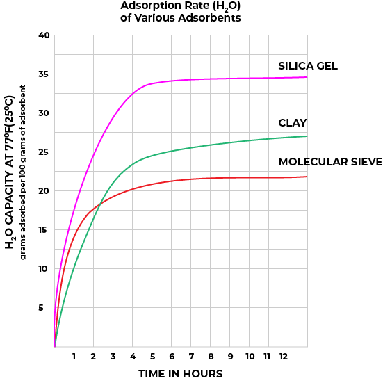
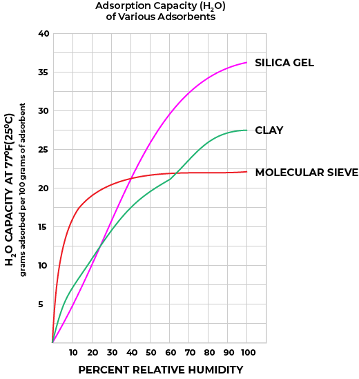
As seen above, molecular sieve – perhaps more common than silica gel in industry applications – performs vastly better than either silica gel or clay at holding RH levels below approximately 40% (at an assumed 77◦F). This is because the equilibrium capacity of molecular sieve at RH less than 40% is greater than that of silica gel and clay. However, molecular sieve is not necessarily appropriate for all assemblies. For example, if an assembly is tolerant of RH in excess of 40% RH, then silica gel or clay may be more appropriate, due to financial expense. The overall cost is a factor and therefore a desiccant decision is sometimes a balancing act between performance needs and expense.
DESICCANT TYPES AND FORMS
BULK DESICCANT
Bulk desiccant is available in beaded and granular forms.
PACKAGED DESICCANT
Packaged desiccant is desiccant contained in breathable packets of various sizes. The packets are commonly Tyvek®, which allows moisture vapor ingress and prevents desiccant dusting.
CUSTOM DESICCANTS
Custom desiccants are made to form fit a customer’s specific product. Custom desiccants are commonly bagged or solid:
Bagged custom desiccants are typically bulk or solid desiccants that are contained in a non-standard sized and shaped bag, usually made of Tyvek®. These bags are heat sealed or handsewn and range in use from electric vehicle battery housings to aerial optics systems.
Solid custom desiccants, commonly known as pressed or formed desiccants, are often composite materials, composed of desiccants and various thermal resistant binding agents. These desiccants often feature greater adsorption capabilities compared to regular desiccant bags or desiccators. Additionally, pressed desiccants frequently feature high thermal resistance and crush strength, and therefore may be used as structural components. However, the greatest benefit lies in their ability to be shaped. Solid custom desiccants are frequently shapeable through machining or other methods to meet strict tolerance requirements in complex geometries and restricted spaces. At the most basic, these desiccants are round pucks; however, they are shapeable to almost anything, providing them with application in virtually every industry.
WHAT IS A DESICCANT UNIT?
Desiccant is often measured in units but how is a desiccant unit defined?
According to MIL-D-3464, a desiccant unit is the quantity of desiccant that will adsorb 3.00 grams of water vapor at 20%RH and 25◦C, and 6.00 gramsat 40%RH and 25◦C. Therefore, a unit of desiccant differs depending on the type of desiccant measured. For example, one unit of silica gel is equivalent to 26 grams, while one unit of molecular sieve corresponds to 28 grams.
HOW MANY DESICCANT UNITS DO YOU NEED?
Military standards do provide a broad answer. MIL-STD-2073-1 states that an enclosure requires approximately 1.2 units of desiccant per cubic foot of free air volume in that enclosure. However, there is a fair amount of assumption and generalization in this recommendation. There are far more sophisticated and accurate methods for determining appropriate desiccant quantities given a specific project or enclosure.
One such method is Hydra20. Hydra20 software considers enclosure material permeation rates, storage and operational environments of the enclosure, desiccant types, and much, much. Given such data, Hydra20 provides optimized desiccant amounts and changeout intervals, as well as recommendations for changes in construction materials and seals to fully optimize for moisture protection.
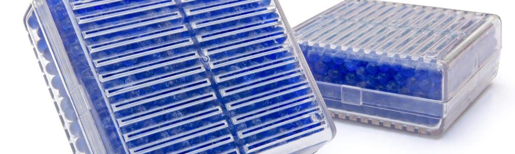
HUMIDITY MONITORING AND HUMIDITY INDICATOR CARDS
Determining desiccant saturation or an enclosure’s internal humidity level can sometimes prove difficult. For this reason, humidity indicator cards (HICs) may be installed directly into the wall of an enclosure, or incorporated into breather valves or desiccators.
A humidity indicator is a small card of blotter paper that is impregnated with a chemical which changes color in reaction to rising RH. This color change makes monitoring a sealed enclosure’s internal environment easy.
Additionally, HICs make it possible to monitor internal conditions of a sealed space without opening that space, which would allow mass water vapor ingress. This is one reason that HICs are commonly used to monitor electronic components during manufacturing and shipping. The component is frequently placed in a clear barrier bag, along with some desiccant and the HIC, then sealed.
HICs may also be installed with humidity indicator plugs. The plugs are aluminum or brass housings with a viewing widow, behind which an HIC may be placed. The plug is then panel mounted to the walls of many types of containers.
Finally, electronic humidity indicators are also available for quick, mass, remote monitoring and tracking. These indicators feature decades long battery life, hourly data recording, and feature data download to Excel via infrared.
PRESSURE MANAGEMENT: THE PROBLEM WITH SEALING AGAINST MOISTURE
To fight against moisture often means picking a fight with pressure and vacuum.
When designing for moisture control in many assemblies and applications, it is necessary to seal a product or enclosure for best results. However, sealing anything opens it up to the affects of pressure and vacuum. Pressure is a very common issue throughout many industries and requires close attention, as most standard methods for pressure abatement have a direct effect on moisture ingress.
METHODS OF PRESSURE AND VACUUM GENERATION IN SEALED ENCLOSURES
There are two common and significant contributing factors to pressure and vacuum issues within the aerospace and defense industry: Temperature and Elevation
DIURNAL TEMPERATURE CYCLING
Pressure and vacuum can occur in a sealed enclosure due to diurnal temperature cycling, the natural fluctuation of temperature throughout a 24-hour period. During the day, ambient temperatures rise, heating a product or container and expanding the air inside, creating an overpressure. As night comes on and temperatures decrease, a vacuum can occur.
If not appropriately planned for, the forces created via diurnal temperature cycling can adversely affect seals on an enclosure, enabling greater ingress of moisture. In turn, the internal humidity level may increase, changing the dewpoint and enabling condensation to form during the night.
General rules for temperature and pressure swing:
- 25◦F temperature swing = 0.7 psi swing
- 35◦F temperature swing = 1.0 psi swing
- 72◦F temperature swing = 2.0 psi swing
It is worth noting that 1 and 2 psi swings are significant. Such swings can cause deformation, especially in non-metal containers, which are often not as rigid compared to metal containers. Large containers are especially susceptible to vacuum draw.
ELEVATION CHANGE
Quite prevalent throughout the transportation and logistics industries, elevation changes will create extreme pressure and vacuum differentials if not planned for. These changes in pressure are a significant issue for enclosures and equipment either shipped or operated in the air, or moved across a range of elevations, such as electrooptic equipment or battery compartments.
Breather valves are the standard for pressure control. However, there are many different valves, each more appropriate for a specific application, and may include an attached desiccant canister if moisture protection is necessary.
An important note for air transport: Most air cargo holds and passenger cabins are pressurized to approximately 11 psi to ensure aircraft safety.
General psi by elevation:
- Sea Level ~ 14.7 psi
- 8,500 ft ~ 10.7 psi
- 25,00 ft ~ 5.5 psi
- 40,000 ft ~ 2.7 psi
PRESSURE SOLUTIONS: UNDERSTANDING BREATHER VALVES
SPRING-ACTUATED BREATHER VALVES
Spring-actuated breather valves are common to most pressure mitigation systems. This type of breather valve is factory set at a specific cracking pressure (also known as an opening pressure) and will open once pressures reach that point. Spring breather valves operate via a poppet and spring method whereby a spring at tension maintains the poppet in a closed position. Once pressure reaches the cracking point, the spring tension is overcome, the poppet is pushed in, and air is allowed to flow though the valve to relieve either pressure or vacuum.
Breather valves may feature:
- Manual release buttons
- Push to release internal pressure or vacuum. This is especially desirable for containers with large lids or robust seals.
- Weather shielding
- Weather shields help to prevent liquid water and debris from entering an enclosure when the breather valve inhales.
- Built-in humidity indication
- Option for a humidity indicator card on the face of the valve. This enables quick visual inspection of the humidity level inside of an enclosure.
Breather valves provide air flow significant enough to mitigate pressure and vacuum in small to large containers. Additionally, water vapor ingress via the valve is kept to a minimum, as a properly specified valve is closed most of the time.
BREATHER VALVE PRESSURE RATINGS
Breather valves are rated for two different pressures: Cracking pressure and full-flow pressure. The difference between these two measurements is another significant source of misunderstanding on part of many design engineers.
CRACKING PRESSURE
Cracking pressure or opening pressure is, of course, the pressure setting at which the valve will begin to “crack”, or open. As defined in the SAE AS27166, the cracking pressure for a breather valve is the point at which the valve enables 1 cubic centimeter per minute of air flow – which is a very low flow rate.
Often, an engineer will request a valve with cracking pressure equivalent to that of the maximum pressure rating for their product or container. However, such a request demonstrates misunderstanding of the difference between cracking and full-flow pressure.
FULL-FLOW PRESSURE
Full-flow pressure is defined as the pressure at which a breather valve is fully open. At this pressure, the breather valve must meet or exceed SAE AS27166, which recommends 12% of an enclosure’s air volume per minute before reaching that container’s pressure or vacuum rating.
For example, a container with 8 cubic feet of air volume and a 2-psi pressure rating will require a breather valve that can flow at least 1 cubic foot per minute of air by 2 psi. Such a valve would typically crack at approximately 0.5 psi.
A word of caution: It may seem tempting to specify a breather valve with very low-pressure ratings in an effort to ensure pressure safety. However, doing so will lead to the selection of valves that open more frequently, which in turn will allow more moisture into the enclosure.
MEMBRANE VENTS
Also known as immersion breathers or GORE® vents, membrane vents are liquid waterproof but allow the permeation of water vapor into and out of a container. Membrane vents are most frequently installed in products or containers to prevent dust and liquid water intrusion.
Membrane vents are most applicable for smaller containers or enclosures requiring protection from liquid water. These vents do not flow enough air to properly protect larger containers from over-pressurization.
INTEGRATED MOISTURE AND PRESSURE PROTECTION SYSTEM
As illustrated through the many previous examples and explanations, there is no one solution to all moisture and pressure variables. To properly protect a sealed product or enclosure against both, it is generally recommended to set up an Integrated Moisture and Pressure Protection System, consisting of a breather valve, desiccant, and humidity indicator. While there are exceptions, this type of system will generally provide the best moisture and pressure mitigation results.
It is worth noting that it is possible to include all components of an integrated moisture and pressure protection system into a single part. Desiccators may consist of a desiccant cartridge attached to a breather valve, which may have the option for an HIC on the valve face.
SPEAK WITH AN ENGINEER TODAY
For assistance in developing an integrated moisture and pressure protection system:
Call: (520) 881-2130 or,